
Topic 05: Arduino Programming
By way of an introduction to programming the Arduino, the Blink example will be used. This simply blinks a light emitting diode (an LED) on the Arduino microcontroller. This is the classic Arduino starter project similar to the first line of programming that anyone learns, namely to write a program to print out the text 'Hello World!'. Detailed instructions on the Blink project have also been covered in many other places such as Arduino and Adafruit.
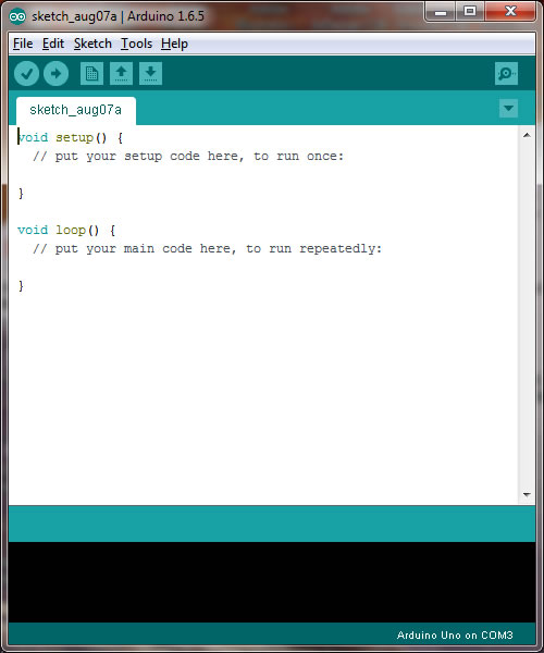
To program the Arduino microcontroller, one must use a software program to write the code and upload it to the Arduino. Arduino referrs to this software as an Integrated Development Environment (IDE). The software is a simple editor and it allows your computer to interact with the Arduino microcontroller. There are now two options for the IDE. One is to use the online IDE, the Arduino Web Editor. This requires that you create an account with a username and password and then you can run the editor from the web without having to install anything on your computer. The second alternative is to install the Arduino IDE on your computer. To do this, the IDE needs to be downloaded from the Arduino IDE download site and installed. If you have reviewed Topic 03 on the Processing programming language, you will notice similarities between the Processing Development Environment (PDE) and the Arduino IDE. They are based on the same platform and are very similar, but they do have distinct differences. Like Processing, the Arduino IDE is a free and open source programming language based on Java. This is what the Arduino IDE looks like once installed and run from a PC:
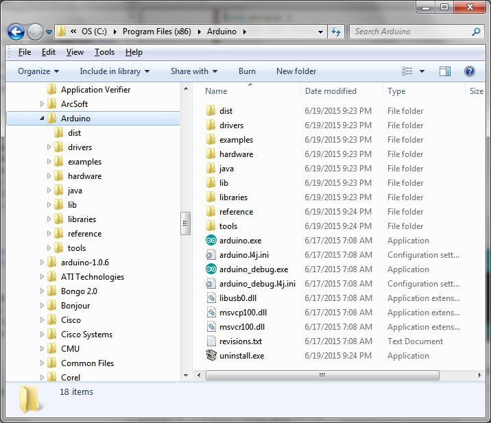
First the Arduino IDE needs to be downloaded and installed. For the Windows operating system, the Arduino IDE is downloaded as a ZIP file. When this is extracted and installed, it should be installed into the 'Program Files' directory as shown below:
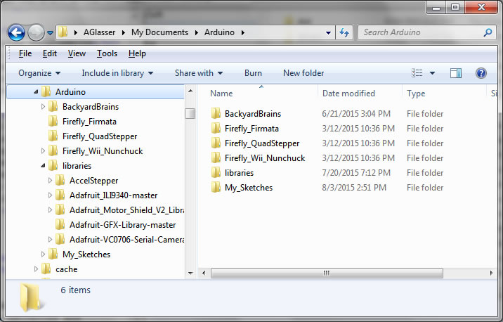
Once the Arduino IDE is installed, drag a shortcut of the 'arduino.exe' file to the desktop to provide an easy-access shortcut icon for starting the Arduino IDE. In addition to the Arduino IDE being installed into the 'Program Files' directory, an Arduino folder should also be created in the 'My Documents' folder. This folder contains additional files for using the Arduino IDE, including any additional programming libraries that can be downloaded from many different sources. It is also into this 'My Documents>Arduino' folder that new Arduino programs will be saved. In the Arduino programming language, a program is called a 'sketch'. A separate folder should be created into which new sketches can be saved. There are many examples of Arduino sketches that are available on the web that can be downloaded and saved to these folders or simply copied and pasted directly into the Arduino IDE and saved as a new sketch.
Connecting The Arduino Uno
Before running the Arduino IDE, it is necessary to make sure the Arduino board is connected to the computer. Detailed instructions for getting started with Arduino on Windows can be found on the Arduino web site. Connect the Arduin Uno via the USB cable to the computer. On doing this, a USB driver will be installed.
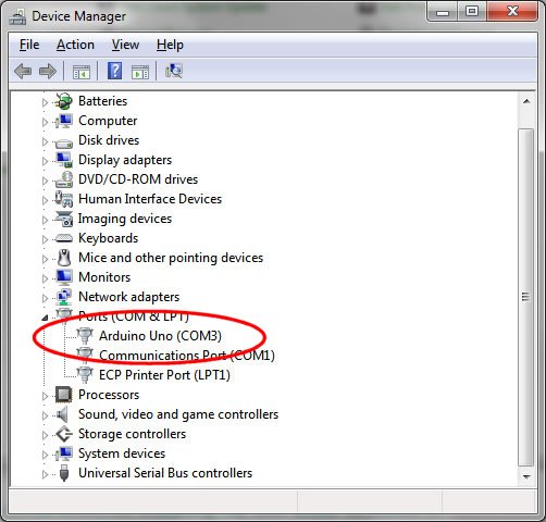
Once the installation is complete, the device manager (Start>Control Panel>Device Manager) should show one of the COM ports configured for the Arduino. In this example below it is COM3:
Now start the Arduino IDE. Under the 'Tools>Board' menu select 'Arduino Uno'. Under the 'Tools>Port' menu select the COM port that the Arduino Uno is connected to (COM3 in this example):
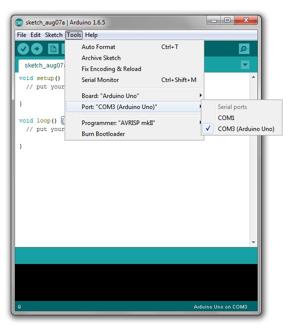
OK, now the Arduino Uno is connected and ready to have a sketch uploaded to it.
About Arduino Sketches
When the Arduino IDE is started, a new blank sketch is created in the editor window as above. This sketch has the form:
void setup() {
   // put your setup code here, to run once:

}

void loop() {
   // put your main code here, to run repeatedly:

}
This blank sketch has two empty functions already created, setup() and loop(), and in-line comments which are followed by the // characters. Comments are not executed with the code, but are just there as, well, comments - to remind you what the code is supposed to do. The '//' symbol is used for 'commenting out' a single line of code or text. If several lines of code or comments need to be commented out, this can be done with matching pairs of symbols in the form of '/*' to start the multi- line comment, followed one or more lines later with '*/'. Everything between the two multilline comment symbols is 'commented out' and does not execute with the rest of the code. The setup() function is run just once when the Arduino microcontroller is powered-up. The loop() function is run repeatidly, as the function name implies. Any code within the loop() function is therefor executed over and over again until the Arduino is powered-down. If the Arduino is reset by pressing the little bkack reset button, the setup() function will be run once again before the code again enters the loop() function.
The Blink Sketch
Normally, creating a sketch would go hand-in-hand with building an electronic circuit, connecting the circuit to Arduino and having the Arduino sketch control the circuit. Building an electronic circuit to go with an Arduino sketch is the subject of the next topic, Topic 06. However, fortunately, the Arduino Uno has one simple electronic circuit already built into it. That basically consists of a light emitting diode (LED) that is tied to digital input/output (I/O) pin 13 of the board. This means we can write an Arduino sketch, upload it to the Arduino board, have it run and see the results of that sketch, all without having to build a circuit.
/*
  Blink
  Turns on an LED on for one second, then off for one second, repeatedly.
  This example code is in the public domain.
 */

// Pin 13 has an LED connected on most Arduino boards.
// give it a name:
int led = 13;

// the setup routine runs once when you press reset:
void setup() {
   // initialize the digital pin as an output.
   pinMode(led, OUTPUT);
}

// the loop routine runs over and over again forever:
void loop() {
   digitalWrite(led, HIGH);   // turn the LED on (HIGH is the voltage level)
   delay(1000);                    // wait for a second
   digitalWrite(led, LOW);   // turn the LED off by making the voltage LOW
   delay(1000);                    // wait for a second
}
Copy this sketch and paste it into the Arduino IDE editor. Click on the verify button ![]() to check the code is legitimate and has no errors. Assuming the sketch checks out OK, the next step is to upload the sketch to the Arduino Uno. Click on the upload button
to check the code is legitimate and has no errors. Assuming the sketch checks out OK, the next step is to upload the sketch to the Arduino Uno. Click on the upload button ![]() to upload the sketch to the Arduino Uno. Once the upload starts, the Arduino LEDs will flash and flicker as the upload proceeds. In a few seconds, once the upload is complete, the board will reset and the sketch will start to run. Notice that the orange LED adjacent to pin 13 will be blinking at about a 1 second interval. So, now Arduino will be in operation and running the sketch.
to upload the sketch to the Arduino Uno. Once the upload starts, the Arduino LEDs will flash and flicker as the upload proceeds. In a few seconds, once the upload is complete, the board will reset and the sketch will start to run. Notice that the orange LED adjacent to pin 13 will be blinking at about a 1 second interval. So, now Arduino will be in operation and running the sketch.
In the next topic, Topic 06, we will assemble this circuit on an electronics prototyping breadboard and connect it to the Arduino Uno.
- an introduction to Arduino
- getting started with Arduino
- how to start coding for Arduino
- the programming reference for Arduino
Go to Topic 06