
Topic 06: Arduino Electronics Prototyping
This topic will provide a demonstration of how to build the simple electronic circuit used for the Arduino Blink sketch. Additional details of this can also be found on the Adafruit Tutorial pages.
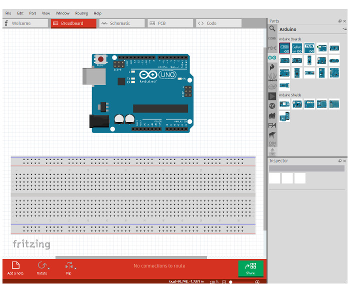
But first, Fritzing offers a free software tool for an open source electronics hardware initiative to teach electronics. In this topic we will use Fritzing to learn about assembling simple electronic circuits to be connected to Arduino. Fritzing has many projects posted to the web site so you can view and download already constructed circuits for Fritzing for you to assemble them yourself.
In the Fritzing software, you can place an Arduino microcontroller with an electronics prototyping breadboard and layout electronic circuits.
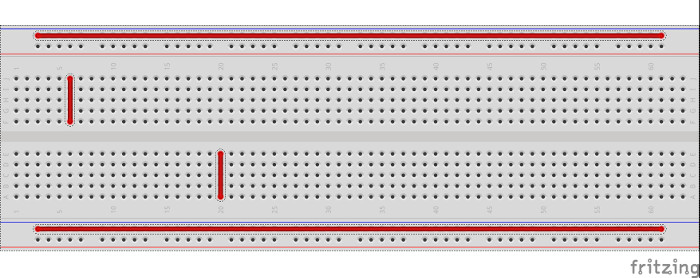
Breadboard pins are connected as shown by the red lines in the image below. If you connect a component to one pin in the red lines, it will also be connected every other pin in the same red line. In general, the two longer horizontal rows of pins along the upper and lower edges of the breadboard are used for power (thin red line) and ground (thin blue line).
The Blink project described at the end of Topic 05 can be designed in Fritzing and assembled in the real world as an simple, independent electronic circuit as is shown in the image below. Fritzing has a library of electronic components and these can be dragged and placed into drawing area to build circuits. A single red LED and a resistor are connected in series between pin 13 on the Arduino Uno and one of the Arduino ground (GND) pins. If this simple circuit is connected and the Blink sketch (from Topic 05) is uploaded to the Arduino, the red LED will blink as instructed by the blink sketch.
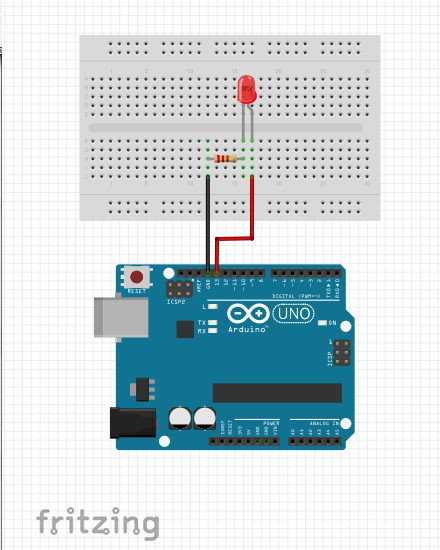
The resistor used above is a 220 ohm resistor. This resistor is required to protect the LED by limiting the current through the circuit. A resistor with greater resistance will limit the current further and will reduce the brightness of the LED. The relationship between voltage, current and resistance is given by the simple equation:
V = i x R
or
i = V/R
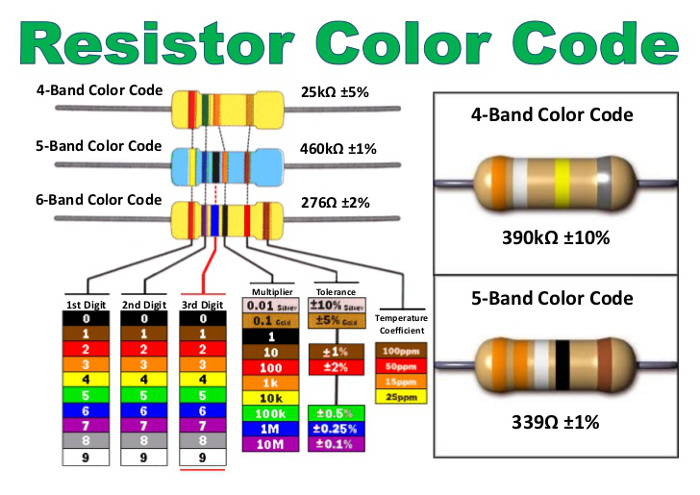
where V is voltage, i is current in units of Amperes and R is resistance in units of ohms. If the resistor is not used and the LED is connected directly between the 5V power and ground pins, the LED will burn out. The resistance of the resistor is read from the color coded lines on the resistor, in this case red, red, brown. The resistance of a resistor can be determined from the resistor color code table below. This is a 4 band resistor, so the first three color bands represent the resistance.
Go to Topic 07.