Adrian Glasser
This blog is about an EggBot to decorate Easter eggs.
The local village shop was organising an Easter egg decorating competition to raise funds for the village hall. Anyone can vote for their favourite decorated egg through a donation in a jar next to each egg. At the end of the day, the donations made for each egg are added up to see which one is the winner.
I don't recall the last time I decorated an Easter egg. I've certainly not done this recently and judging by decorated egg photos I have seen online I don't have the artistic creativity to compete. However, I have enjoyed reading many online articles about home-made robots for decorating eggs. I have often thought this would be a fun and rewarding project to undertake, but have never got around to doing it. When Sally mentioned that they were going to be having the decorated Easter egg competition, I thought that this would be a great excuse to buckle down and try making the egg decorating robot. These are often described as EggBots or a SphereBots. Since an egg is not too dissimilar from a sphere, if something works on a sphere, it should also work on an egg, and vice versa. There are many web pages, blogs, designs, open-source software applications, descriptions and tutorials on EggBots or SphereBots. In fact, several versions are available to buy commercially. So, there is no shortage of resources on how to design, make and operate these little robots.
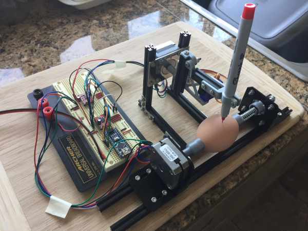
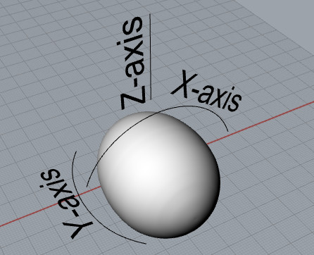
The idea of an EggBot is to clamp the two 'pointy' ends of an egg along its long axis with a stepper motor on one end to rotate the egg around 360 degrees. The rotation of the egg is around the X-axis. A pen is held above the egg with a servo motor which lifts the pen up off the egg or lowers the pen down onto the egg (this represents the Z-axis). The pen is rotated through about 90 degrees, along an axis perpendicular to the X-axis by a second stepper motor so that the tip of the pens maintains contact with the 'spherical' surface of the egg. This rotation of the pen represents the Y-axis. A microcontroller controls the movements of the motors. Through controlling the X, Y and Z axes, the egg and the pen can be moved together to draw on the shell.
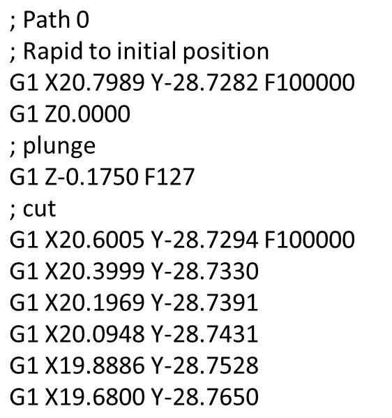
An EggBot works much like a 2D plotter where a pen is moved in an X- and a Y-direction to draw on a flat page and the pen can be raised up off the page or lowered down onto the page. An EggBot is basically a 2.5-axis, computer numerically controlled (CNC) machine. The 2.5 axis means that it has two stepper motors (for X and Y axis movement) and a servo motor (considered the other half axis) to raise or lower a milling bit (in the case of a milling machine) or a pen (in the case of a plotter or an EggBot). A 3-axis CNC machine would be like many desktop 3D printers which have three stepper motors, one each for the X, Y-axis and Z-axes. Of course, one major difference between an EggBot and a 2D plotter is that the egg is rotated rather than the stepper motor moving a pen horizontally over a flat page. Since an EggBot is a simplified CNC machine, this means it is well suited to being controlled with 'gcode'. Gcode is basically the universal language of CNC machines and is simply a set of sequential commands or instructions that are sent to the microcontroller controlling the motors on CNC machines. The gcode instructions basically identify the direction, distance and speed that each motor must move to get the pen or the milling bit to the next location in the design that is being drawn on a page or milled out of a piece of wood.
I've not built any CNC machines before or had any experience with gcode, but this is a great project to do just that. Fortunately, I had most of the parts and supplies on-hand needed to make an EggBot. This included two stepper motors, one servo motor, a microcontroller, and the support structure to hold everything together, which in my case was a MakeBeam kit of 10 mm aluminium extrusion.
All the software required is available as open-source and there are many possible different ways for doing this. An Arduino Nano microcontroller serves as the brains for the electronics to control the stepper motors and the servo motor. GRBL is open-source firmware for the Arduino platform (ironically, GRBL stands for Garble). GRBL can be installed as a library on the Arduino Integrated Development Environment (IDE) and GRBL is then flashed to the Nano by uploading a one-line Arduino sketch. This GRBL code basically waits for gcode commands to be sent to the Arduino and then interprets each line of gcode that is sent and makes the appropriate movements of the X- and Y-axis stepper motors and the Z-axis servo motor.
To get the gcode, it is first necessary to start with an illustration or some text that is to be printed on the egg. The illustrations are done in Inkscape, an open-source, vector graphics software program. Everything in the illustration, including any text must be vectors (lines), because that is how the EggBot works, it draws lines. A .svg vector file is saved from Inkscape. This .svg file can then be loaded into JSCUT, a web browser application. JSCUT converts the vector file to gcode. The gcode file can then be saved. This gcode file can then be loaded by Universal Gcode Sender (UGS). UGS connects the computer to the microcontroller through a serial port connection and then sends the gcode, line-by-line, to the GRBL firmware running on the Arduino. A few of the standard configuration setting in GRBL need to be manually modified to get the EggBot to respond correctly. These are the number of steps per millimetre of travel for the X- and Y-axis stepper motors and the speed and acceleration for the stepper motors.
Several of the parts needed for the EggBot were custom designed with computer aided design software (CAD) and then 3D printed. These included the parts needed to hold the ends of the egg, the pen holder, parts to hold the MakerBeam pieces together, a bracket to hold the servo motor, a hinge for the up and down pen movement, etc. These were all designed to fit with and bolt to the 10 mm MakerBeam aluminium extrusion.
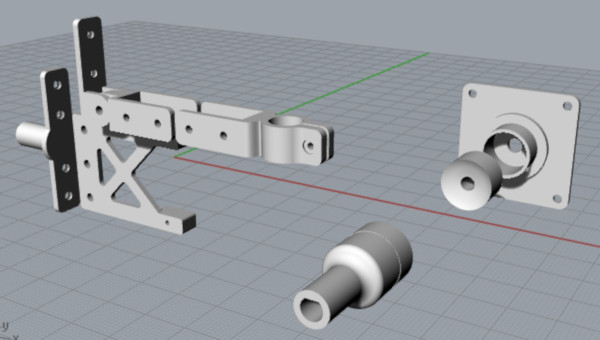
A compression-spring mechanism with rotational bearings was used to hold the egg on the more pointed end. This allows adjustment of the compression force holding the egg so that the egg is held firmly, but not crushed. Small pieces of a soft rubber material were glued to the ends of the 3D printed parts holding the egg to allow the egg to be gripped so that the egg does not slip when it is rotated by the stepper motor. This turns out to be critically important for the EggBot to ensure that the design being drawn on the egg all 'lines up' correctly because when the gcode for the design is generated, it does not always come out in what might appear to be a logically sequential order. So, for example, the EggBot needs to return to dot the letter 'i' long after the 'i' might have been printed and it is rather important that the EggBot gets back to exactly the right place to dot the 'i'.
The eggs were blown by making two small holes in the ends with a Dremel drill and breaking the yoke with long skewer inserted through one of the holes. The eggs were used for omelettes for lunch.
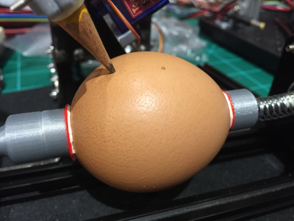
The first few test runs of the EggBot were done with pencil because the pencil marks can easily be washed off the eggs with a little soapy water. A few adjustments were required to get everything working correctly, including adding an elastic band to pull the Z-axis down so the pencil or pen tip remains in firm contact with the surface of the egg shell and adjustments to the positions of the stepper motors to ensure that the egg was centred and the rotation of the pen positioned at the centre of the egg.
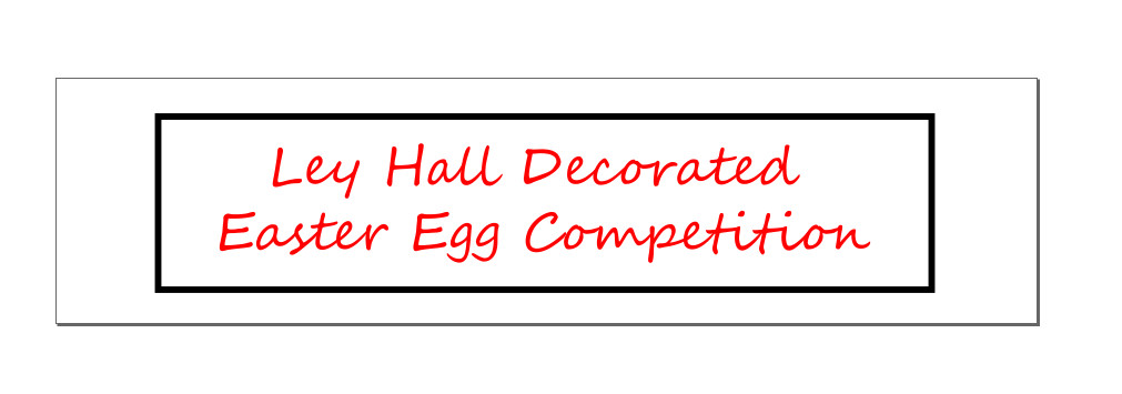
To draw on the egg with more than one colour first requires arranging the different parts of the original illustration in Inkscape in different layers, one layer for each colour. In this case the text was in one layer and the rectangular frame in a second layer. The colours used in Inkscape are just for illustration and to verify the appearance of the colours chosen based on the pen colours available. Each layer needs to be saved as separate .svg file and converted to separate gcode files. To get the different colours on the egg, each part of the illustration needs to be sent to the EggBot as a separate gcode file and the pens needs to be physically switched before sending the gcode for the next part of the illustration. As mentioned above, the EggBot does not always draw or write things in the logical sequential manner that humans would, so as can be seen in the short video clip below, the text is actually being written backwards.
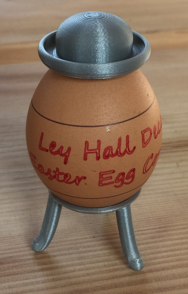
The first decorated egg was given to the village shop to put on display to publicise the Ley Hall Decorated Easter Egg Competition. In addition to having text printed on the egg, a 3D printed stand and top hat were designed and 3D printed for the egg.
Just a couple of weeks ago, before Sally mentioned the Easter egg competition, I knew very little about CNC machines, gcode, how to generate gcode, how to send gcode to a CNC machine or how to operate a CNC machine. Now, although far from being an expert, I have a much better understanding of this process, I have some practical experience with it and I have learnt a great deal from it and had a lot of fun doing so. For me, a good day is when I learn something new. I've had many great days doing this project. Now all that remains is to come up with a design to decorate an egg for the competition.