
Adrian Glasser – Land of Iron volunteer
This blog will describe development of a photogrammetry trolley.
Paul was trying to do photogrammetry of a stone bridge that included the external structure of the bridge as well as under the arch of the bridge. Photogrammetry is the process whereby a 3D model of an object can be reconstructed from multiple overlapping photographs of the structure. The arch under the bridge had had years of build-up of soil restricting the space under the bridge, making the photography challenging. Paul had to crouch down to get photos through the underside of the arch and the lighting was challenging and variable away from the daylight at the entrances to the arch.
I suggested that one approach to do photogrammetry under the arch could be to use a sled pulled by a rope along tracks laid down on the soil. The tracks could simply be one or two 6 ft long 2x4 pieces of wood. Such a sled could carry the camera and battery powered lights to illuminate the field of view of the camera as it was dragged along the tracks. The camera could be triggered automatically and periodically as the sled is dragged along the tracks. I envisaged an Arduino microcontroller measuring the distance travelled along the track and triggering the camera to take a photo at set intervals along the track. This would entail several passages of the sled along the tracks with the camera oriented at different angles on each pass to cover the entire under surface of the underside of the arch. If the arch was long, then an initial section could be photographed in this way, then the 'tracks' lifted and moved end-on-end until the full length of the arch had been photographed. This seemed rather laborious. After further discussion, the sled became a trolley carrying several cameras all oriented at different angles and all triggered simultaneously. This would solve the problem of having to make several passes through the arch. Although triggering several cameras simultaneously is straightforward, there aren’t too many people who have several cameras. It would be possible to use smart phones, since the cameras on smartphones are fairly descent these days, and it would be possible to trigger several smart phones cameras simultaneously. The challenge of getting several smart phones could be solved by a group of people going out together and each contributing one phone. However, that is still logistically challenging. So, an alternative would be to use just one smartphone and progressively rotate the phone through 180 degrees capturing multiple overlapping photographs as the trolley moves along the arch, stopping every few feet along the track for the duration of the multiple exposures to cover the full length of the arch. Then the thought of using a remote controlled vehicle for the trolley came to mind.
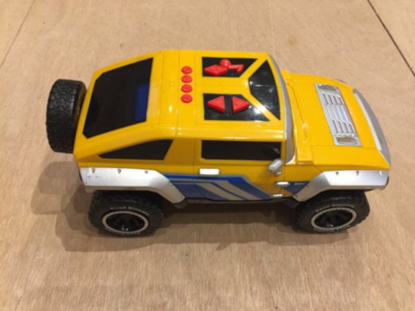
I happened by a car boot sale at which various old, used, battery operated toy cars were being sold. I examined a few of them and decided upon a fairly large 'Hummer'. The size seemed appropriate and the fact that this rather simple toy car had no turning ability was appealing. There were a few buttons on the roof which suggested forward and reverse motion and a variety of sounds. The sales person assured me that it worked, but it had no batteries in it. I took my chances and bought it for the asking price of £3.00. On installing the batteries and unjamming one wheel, all the functions worked. It is runs on a DC motor and pushing the forward or reverse button elicited a few annoying sounds and then sent it careering forward or backward for a fixed distance of about 5 meters. That's basically all it did. It was ideal for the intended purpose.
Based on this toy car, the plan was to disassemble it, to evaluate the circuitry to see what might or might not be usable and then to hack it to allow an Arduino microcontroller to control it. Since it uses a DC motor, my initial thought was to run it forward for a set distance, either with an encoder attached to one axle or for a fixed time interval. On the chassis, I'd install a rotating gimbal holding a smartphone and trigger the camera from the Arduino.
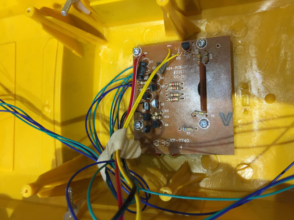
There was not much to the circuit controlling the car. Other than running the DC motor, the primary 'features' of the toy were a variety of audio tracks, including alarms, engine starting, wheels screeching, an annoying jingle and a cheesy voice-over. These sounds were in a single simple chip cemented over.
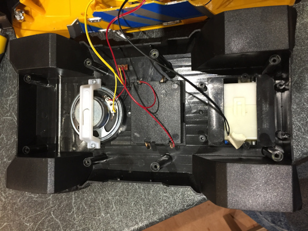
Similarly, there was not much hardware inside the car. There was a speaker wired to a switch, the enclosed gearbox around the rear axel and the battery compartment.
For the initial testing of the software, I decided to have the system controlled by a infrared (IR) remote. It's pretty straightforward to get an Arduino microcontroller to recognize the different buttons on a IR remote with an IR detector. Having implemented that, it means that at least initially, the programming logic can be very simple in the sense that each individual function is controlled by a different button on the remote. This facilitates the software development because each piece of code controlling each individual function can just run separately and independently, when invoked by each individual button press. When all the individual functions are working, then the more complex process of integrating all the individual functions can be tackled.
IR Remote Controlled Trolley
The toy car has no steering capability and the front wheels are fixed in the straight-ahead orientation. Unfortunately, the car has a left-veer bias. So for now, for the goal of having this run on the wood tracks, I've had to erect a barrier on the left side of the left track. This is not ideal because it creates a lot of friction and can in some cases slow the car to a stop. I'm considering better ways to fix or address this. The power button on the IR remote toggles the DC motor on and off. It's also possible to increase or decrease the speed of the DC motor from the IR remote.
To get this all working I'd need to have each of the following functions operational:
- run and stop the DC motor to make the trolley move
- install a break to stop the trolley moving when power to the DC motor is turned off
- install and monitor an encoder with an IR sensor to record the distance moved
- or replace the DC motor with a stepper motor to be able to control the distance travelled
- construct a gimbal system to hold and rotate a smartphone
- have the servo motor turn the gimbal to 0, 90 or 180 degrees to install or remove the smartphone
- have a servo motor turn the gimbal to rotate the smartphone through 180 degrees
- have the servo motor turn through 180 degrees in a fixed number of steps of a fixed angle with a pause at each step to take the photographs
- have the smartphone camera triggered to take the photos
Not all of these individual functions are currently working, but readily available solutions for all of them exist and are on hand. I've some testing to do still to converge on the ideal approaches for each. We'll get to those eventually. Once each one has been addressed independently, I'll bring it all together.
Smartphone Gimbal
A prototype gimbal system has been constructed from MakerBeam aluminium extrusion. A servo motor on one end is connected to the MakerBeam with ThermoMorph plastic. The other end has a bearing to reduce friction during rotation. The MakerBeam is stronger than needed and as a consequence also heavier that desired. A perfectly adequate gimbal could readily be constructed from 3mm laser cut plywood. Perhaps that will be implemented in the future. Fortunately, and quite by chance, the width of the MakerBeam gimbal system fits perfectly into the toy car cassis, requiring no screws to fix it in place.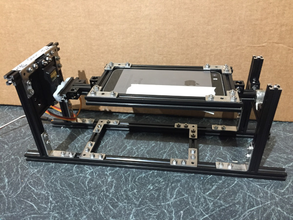
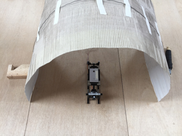
Photogrammetry Trolley
Bluetooth Remote Camera Trigger
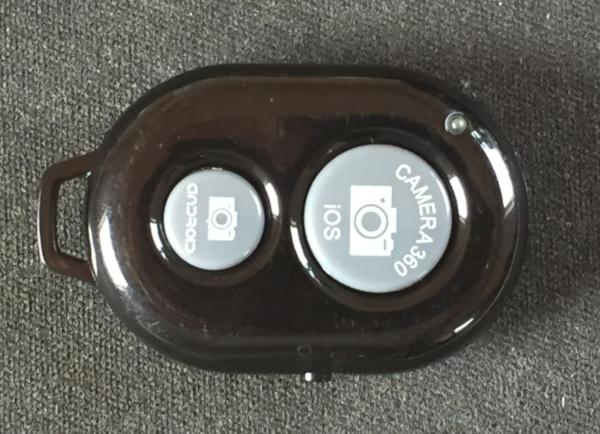
Next we have to trigger the smartphone camera. I am using an iPhone. Commercially available Bluetooth selfie-remotes are available for only a couple of bob. Most have two buttons, one for an iOS and one for Android phones. When you turn the remote on and the iPhone Bluetooth is on, the iPhone finds the remote and the remote can be paired to the phone. When the camera is activated on the iPhone and the appropriate button on the remote is pressed, the Bluetooth remote will trigger a photograph.
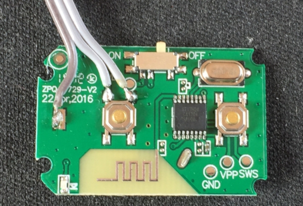
After taking the remote apart and soldering three wires, one lead to the ground, and the other two leads to the terminals of the push-button, this remote can then be triggered externally from an Arduino.
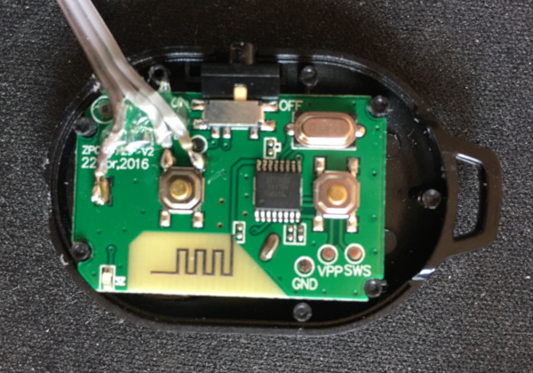
The case of the remote needs to have a hole cut into the side to allow the case to close after the wire has been attached. Some hot glue applied near the end of the wire on the circuit board and to the case under the wire will help to prevent the wire from being pulled off.
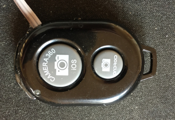
If the wiring is done carefully, the remote goes back together easily. A little hot glue around one edge will keep the remote together and still allow it to be pried open from the other end if that is ever needed.
With the remote reassembled, the wires can be attached to the Arduino microcontroller. The ground wire goes to the Arduino ground. The other two wires go to the collector and emitter leads of a PN222A transistor. An Arduino digital pin (pin 3 in this case) goes to the base pin of the transistor. When the Arduino pin 3 is set HIGH, this drops the resistance across the collector and emitter pins of the transistor and effectively shorts out the push button, just as if the push button were being pressed. A short delay is required before returning the pin 3 output to LOW again. If this output is left height too long, the iPhone triggers multiple repeated photos (16 in one second on my phone). This could be a useful function for another project, but is not wanted here. Here's a bit of code to trigger the Bluetooth remote.
int BluetoothPin = 3;
//*****************************************
void setup() {
  pinMode(BluetoothPin, OUTPUT);
  analogWrite(BluetoothPin, LOW);
}
//*****************************************************
void loop() {
	// do somethng in here to trigger the remote and call the take_photo() function
    // im my case I am using an IR remote, so that take_photo() function gets called
    // when the appropriate button on the remote is pressed
}

//*****************************************
void take_photo() {
  // send signal to transistor to short Bluetooth button
  digitalWrite(BluetoothPin, HIGH);
  delay(200);
  digitalWrite(BluetoothPin, LOW);
}
With that done, the Arduino can then get programmed so that the iPhone camera is triggered each time the servo moves through the sequence of 180 degrees in 20 degree steps. I just call the take_photo() function each time. To test this out, I built a small arch out of cardboard and drew some stones on the cardboard with some numbers to show the progress of the camera around the arch.
It works most of the time. Occasionally, the Bluetooth remote is triggered by the Arduino (this can be seen on the remote because a blue LED illuminates each time it is triggered), but the iPhone camera does not trigger. I think it might be that the delay between sending a HIGH and a LOW signal is too short - that's the 200 ms in the code above. I'll work to see if I can figure out why the camera is occasionally not being triggered. Here below is an animated gif file of all the images captured by the camera as it is rotated around the inside of the arch. The perspective is a little disorienting, but imagine you are lying on your back under the arch and rolling from the left around to the right. The numbers increment from 1 to 9 where the floor meets the walls of the arch and there are 10 individual photos.
Infrared Optical Sensor
One problem the toy car has is that it is controlled by a DC motor. This means that there is no easy way to control how far the car goes before stopping to take photos each time. A stepper motor or a servomotor allows one to control how many revolutions the motor makes. To do this with a DC motor requires some additional steps. In an effort to see if we can control how far the trolley goes each time, an infrared optical sensor needs to be implemented to count the DC motor revolutions to determine how many times the wheels have rotated.
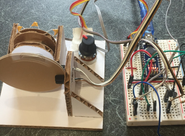
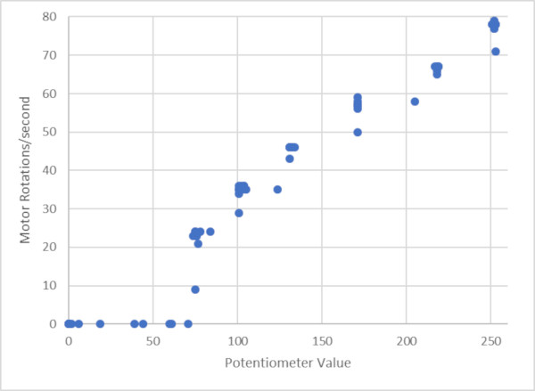
A side project has been undertaken to measure the number of rotations of a DC motor. This has been implemented with a optical sensor harvested from an old printer. A small cardboard rig has been built to hold a DC motor, to control it's speed and to hold the optical sensor in the correct position next to a wheel attached to the DC motor. This was implemented with an Arduino Nano and using interrupts to count the motor rotations per second. To check that the circuit is counting the DC motor revolutions correctly, I have compared the ouput from the Arduino code with a direct measurement from an oscilloscope.
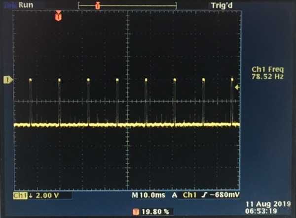
The Arduino sketch records the same number of revolutions per second for the DC motor as the oscilloscope. The DC motor speed is controlled by a potentiometer and the maximum speed that the DC motor achieves is about 80 revolutions per second and the Arduino sketch is able to record this accurately. Here is a graph of the relationship between the potentiometer value and the motor speed. There is a little delay each time the potentiometer is adjusted until the motor achieves the set speed, and there is a little hysteresis (not shown here) when turning the potentiometer to increase the motor speed or turning it to decrease the motor speed. The DC motor only starts to turn when the potentiometer hits a value of about 75 on the way up.
The Arduino sketch has now been modified to count the absolute number of motor rotations and to then stop the motor when the set number of rotations has been achieved. This works well, so the distance that the trolley moves can now be kept track of. However, the DC motor for the trolley needs to be powered quite high to enable the inertia of the weight of the trolley to be overcome to move the trolley. This means that the trolley moves quite fast each time and then the momentum from the movement means that when the DC motor power is cut at the appropriate distance, the trolley does not stop there. So in addition to computing the distance that the trolley moves, a brake will have to be implemented to stop the trolley once the set distance is moved.
Both the optical sensor and the brake will also have to now be implemented on the trolley. Some modification of the trolley chassis will need to be undertaken to achieve this. Watch this space for an update.